| Family Events | |
| Genealogy | |
| Running | |
| Web | |
| Miscellaneous | |
| Contact |
Digital Sculpture Techniques
How to Apply the Principles of Traditional Sculpture to Make Stunning 3D Characters
by
Bay Raitt and Greg Minter
All images created by Bay Raitt. Copyright Nichimen Graphics 1998.
This article originally appeared in the August 1998 issue of Interactivity magazine.
Even among technically oriented artists, 3D is perceived to be a left-brain medium And, in large degree, it is. The mathematical rigors of representing 3D objects, complete with environmental effects such as light, continue to leave their mark on even the most user-friendly modeling and animation tools. Newcomers have to learn a new way of thinking while even the most experienced 3D artists continue to find new uses for abstruse features. once you step into the third dimension, you leave the familiar world behind.
Searching for the keys to more productive 3D, nearly everyone misses an obvious, quite familiar, extremely relevant discipline: sculpture. Considering 3D modeling as a process of sculpting suggests powerful techniques that can simplify difficult 3D tasks, especially the task of modeling characters for animation.
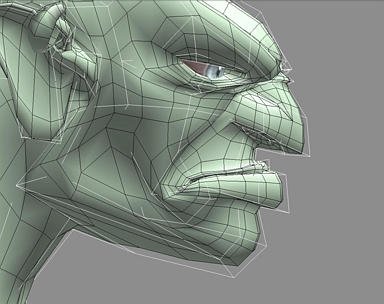 |
Figure 1. When a sculptor chisels a form from a block of marble, the block becomes smaller. Similarly, a control object generates a smaller derived surface. |
In this article, we'll look at ways to manage the complexity of even the most elaborate character animation using the techniques of volume modeling, derived surfaces, and edge loops. The workflow described mimics the traditional sculpting process and lets you generate output in a variety of resolutions for VRML, games, animation, film, or print from a single source. This approach is an excellent alternative to the shortcomings of NURBS modeling and it's well on its way to becoming a primary paradigm for 3D production. In fact, Pixar has started to reorient their entire production pipeline to accommodate it.
At the moment, Nichimen's Mirai and Kinetix 3D Studio Max are the only tools that fully support this approach (MAX's implementation of derived surfaces is only partial). NewTek LightWave's metaNURBS capability does the trick for high-resolution output only.
Volume Modeling
A sculptor starts by rapidly defining the volume, then concentrates on refining the surface. In 3D, this method is known as volume modeling, the process of growing, extruding, and manipulating edges, faces and vertices of a polygonal primitive such as a cube. In contrast, when you work with a modeler that manipulates higher-order surfaces, including NURBS, patches, and metaballs, you start by defining an object's surface first, and then modifying its volume. To a traditional sculptor, this approach puts the cart before the horse.
Sculpting in the digital realm lets the sculptor work naturally, but with a superset of the tools available to the traditional artist. He can twist a model around its axis, duplicate its geometry around a face, even squash and stretch it with impunity, secure in the knowledge that any changes can be undone. The ability to save work at different stages or undo multiple topological changes is beyond the realm of possibility when you're working with clay, stone, or other physical media. A sculptor working on a clay model to be digitized has no such freedom.
Moreover, because you're working with a relatively simple mesh rather than higher-order surfaces, you can do most of the work in real time. The traditional knock against polygonal modelers has been that machines bog down under the load of a high-polygon, textured model. This was true a year or two ago, but today you can pick up a fully loaded 400 MHz dual-Pentium machines with screaming 3D board for a couple grand. A machine like that will move even high resolution models around at head spinning speed.
The creative benefits of speed and simplicity may seem obvious, but many 3D artists work with meshes so complex that only parts of it can be seen on the screen at any given time. In this situation, you forfeit the spontaneity essential to creating rich, expressive forms. Volume modeling lets you focus on building an efficient low resolution form while taking advantage of the power of your software and hardware to generate higher resolution versions using derived surfaces.
Derived Surfaces
A typical character's low resolution form might be 500-1000 polygons, depending on its structure. While a character of this resolution is probably acceptable for many real time applications, it's definitely unacceptable for production animation, film, or print. Fortunately, most of the current generation of polygonal modelers can generate a separate higher-resolution mesh automatically from a lower resolution version via smoothing. The higher resolution version is referred to as a derived surface.
Using Mirai, MAX, or LightWave, the original low resolution object can be used as a control object to manipulate the derived surface. If your software takes care of everything it should (such as maintaining texture integrity on subdivided surfaces), you'll never have to manipulate the derived surface directly.
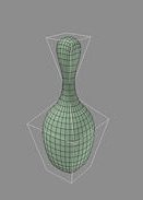
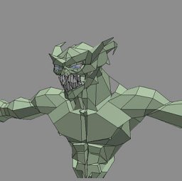
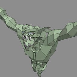
When a sculptor chisels a form from a block of marble, the block becomes smaller in dimension. The control object serves as a bounding volume for the derived surface, simulating this fundamental principle of real-world sculpting (Fig. 1). The control object can be smoothed once, twice, or as many times as necessary, depending on the output resolution you require. Figure 2 shows the evolution of a character from an artist's sketch to a high-res version. The figure in the middle is the control object, the one to its right is the derived surface, and the figure to the far right (also a derived surface) has been smoothed twice and rendered.
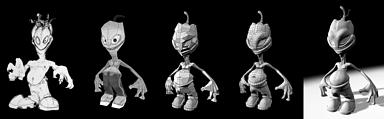 |
Figure 2. The evolution of a character. The artist's sketch is at far left. To its right is a quick low-res model that has been textured for reference. The figure in the middle is the finished control object, the one to its right is the derived surface, and the figure to the far right has been smoothed twice and rendered. |
Modeling for Smoothing
The trick is to build a control object that generates the derived surface you have in mind. To accomplish this, it's necessary to understand the smoothing algorithm of your modeler.
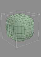
Consider smoothing a simple cube (Fig. 3). A higher resolution mesh is derived from cube, while the cube itself is unaffected. Scaling a face on the control object simultaneously updates the derived surface (Fig. 4). Small topological changes, such as adding edges around the middle of the cube can create a very different high resolution mesh (Fig. 5); the additional points on the control object will let you manipulate the shape of the object further. Maintaining sharp edges on the derived surface is achieved by pinching edges closer together on the control object (Fig. 6).
 |
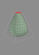 |
Figure 3. A low-resolution object generates a higher-resolution derived surface. In Mirai, you'd create a cube, select the body of the object in the body edit menu, choose Smooth, and select the With History option.* |
Figure 4. Scaling a face on the cube simultaneously updates the derived surface. |
 |
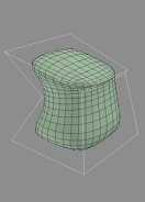 |
Figure 5. Small topological changes, such as adding edges around the middle of the cube, can create avery different high-resolution mesh. |
Figure 6. Maintaining sharp edges in the derived surface is achieved by pinching edges closer together on the control object. |
| * To achieve the same results in Kinetix 3D Studio Max, you'd create a reference object and add a smoothing operation to its stack, then shade the reference object and make it insensitive. In NewTek LightWave 3D, create a cube and hit TAB, which replaces the cube with a smoothed metaNURBS object. The vertices of the cube are still visible and available for manipulation if you hit TAB again. | |
A basic principle of smoothing—and a very important one—is that although the derived surface is smaller than the control object, it intersects the control object at the midpoint of each of the control object's faces. These points are the key to predicting the results of smoothing. If you need a sharp edge, create a face with a midpoint at the intended edge and then add small faces around it (Fig. 7).
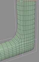 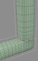 |
Figure 7. If you need a sharp edge, create a face with a midpoint at the intended edge and then add small faces around it. |
Mirai lets you remove unwanted topology from the derived surface without disrupting the relationship between the control object and the derived surface. You can do this by using Dissolve on segments and Merge Faces on collections of faces. (If left unreduced, the generated mesh has roughly four times the polygons of the original control object.)
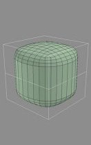 |
Figure 8. Mirai lets you reduce polygons on the derived surface without disrupting the relationship between the control object and the derived surface. This lets you optimize polygon count of the derived surface while maintaining the overall shape. |
By combining these techniques, surprisingly complex shapes can be created in just two or three steps. Figure 9 shows the effects of extruding faces or points, beveling corners, co-planaring edges, and other simple operations.
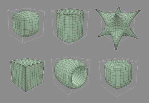 |
Figure 9. Starting with the cube (top left), the effects of extruding faces (top middle), extruding points and then beveling corners (top right), co-planaring edges (bottom left), bridging a hole through the center (bottom middle), and vertex-subdividing a face (bottom right). |
Modeling for Animation
Beyond the issue of how a control object reacts to smoothing, it's necessary to attend to the derived surface's potential for animation. It needs to look right from any angle, and it needs to look right in all the various poses it might assume as its joints bend. To create these results, your modeling process should take into account the three fundamental aspects of dynamic form: contour, silhouette, and movement.
Silhouette is a model's 2D outline from any given angle. A standard approach in traditional sculpture is to look at your work from as many angles as possible. When the silhouette looks correct from any angle, you're done. To avoid adversely affecting the silhouette in one perspective while you're changing it in another, it's best to constantly adjust the camera position while you're working. Many artists end up working with the camera aligned on just the X, Y, and Z planes, especially when the model becomes too complex to spin around freely. Fortunately, a control object should never become so complex that you can't spin it around.
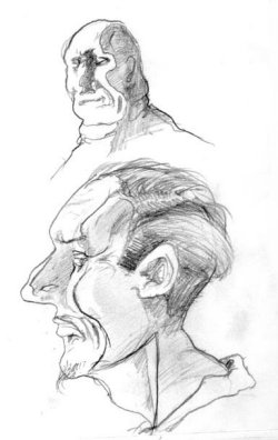
Contour is the 3D manifestation of silhouette. Among other things, it defines the way light falls across the model, making shadows a helpful tool in modeling. If you study the way a harsh light falls across a character's head, one can see how the shadow forms a strong line running down the support bone of the temple, across the wrinkles on the side of the eye, along the cheek to the jaw line, and then down the neck (Fig 10a). Shadows can tell you at a glance how an object projects in 3D space. Watch them carefully as you work, and with practice, you'll be able to recreate a 3D representation fairly accurately from only a 2D image (Fig. 10b).
 |
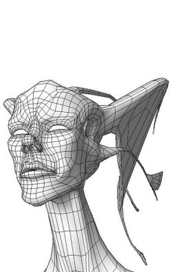 |
Figure 10. Harsh light falling across a three-dimensional form reveals its contour. With practice, you'll be able to recreate a 3D representation fairly accurately from only a 2D image. |
|
The lighting within your modeling environment creates the shadows that help you evaluate silhouette and contour. Therefore, it's important to understand how the light behaves in a realtime modeling environment, viewed in perspective camera mode. For each pixel, the computer calculates the way a ray of light bounces off the surface of the polygon and into the camera. The greater the angle of the bounce, the darker the pixel.
However, realtime hardware typically lights a scene based on the normals only (for speed reasons). That is, real time renderers do shading, not shadows. If a side-lit character faces the camera and opens its mouth, any polygons on the inside of his mouth whose normals face the light will also reflect it. This is something to watch out for when you examine contour and silhouette.
In most modeling packages, a light is "fixed" to the camera and moves with it automatically. In this situation, no matter how you look at the model, it will be lit as though you were wearing a miner's hat with a headlamp (Fig. 11). Generally this is helpful, since the model will never pass into shadow. But if the way a shadow falls across a model is integral to your modeling process, a different lighting setup is in order.
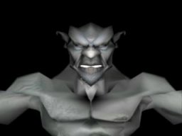 |
Figure 11. In most modeling packages, a light is "fixed" to the camera and moves with it automatically. This setup obscures a model's contour. |
Replace (or augment) the camera's default light with two infinite lights that also move with the camera. Aim them directly at each other across the model diagonally, one pointing downward from the upper right, one pointing upward from the lower left, and dim the lower light to 50% (Fig. 12).
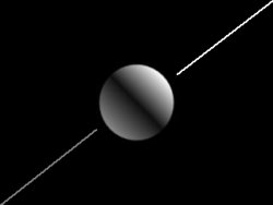 |
Figure 12. To make contour more visible as you model, replace (or augment) the camera's default light with two infinite lights that also move with the camera. Aim them directly at each other across the model diagonally, one pointing downward from the upper right, one pointing upward from the lower left, and dim the lower light to 50%. |
When used to light a model, this setup brings the contour into sharp relief (Fig. 13).
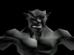 |
Figure 13. The modified lighting setup creates shadows that bring contour into sharp relief. |
Keep in mind that your object is going to move, twist, and bend, and that the static form you're creating will need to look good in any position. Test the model's flexibility and evaluate the results in terms of silhouette and contour. There's no need to model characters in the familiar frog-dissection pose. The traditional reason for this pose was to make it easier to skin the vertices to appropriate bones and make it easier for the animator to define muscle behavior and the software's skinning algorithm is robust, you can work on the model in a more natural pose, which yields a better sense of form, weight, and personality.
To see how the derived surface will react when the control object is posed in extreme positions, rotate limbs straight up, straight out, and as far back as they can move. This will reveal problems such as shearing or intersecting faces around the moving joint. The geometry of the control object must accommodate a full range of motion.
A common mistake is to add geometry around areas that aren't behaving correctly. Unfortunately, even with the added geometry, models like the one in Figure 14 break down rapidly when animated. A human shoulder joint is a floating joint that moves around the center of the chest, not a ball-and-socket joint like the hip, so the extra geometry has been added in the wrong place.
More important, the extra geometry in Figure 14 makes no contribution to either contour or silhouette—it's wasted data.
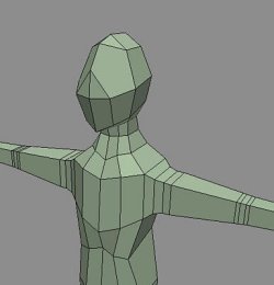 |
Figure 14. The geometry that has been added to this model's joints will break when it's animated. More important, the extra geometry makes no contribution to contour or silhouette. |
Figure 15 shows a better example of how to add geometry around a shoulder joint. By adding geometry that flexes correctly during animation, you can make shoulders, armpits, and any other dynamic forms a good deal more lifelike.
 |
 |
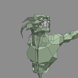 |
Figure 15. This model's shoulder has been built correctly, contributing to the model's contour and silhouette while allowing for shoulder-type motion. By adding geometry that flexes correctly during animation, you can make shoulders, armpits, and any other dynamic forms a good deal more lifelike. |
Edge Loops
Creating good contour edges on the control object has another beneficial effect. If you shape them properly, they'll mimic the actual muscle structures that make up the body of the model. Selecting vertices along these edge loops lets you manipulate the model as if you were moving the underlying muscle. The key is to define an object topology made up of such edge loops (Fig. 16).
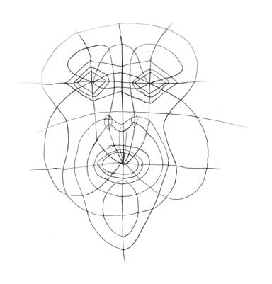 |
Figure 16. A control object's edges can mimic muscle structures. Adjacent vertices form loops that allow you to manipulate a model as though you were moving the underlying muscles. The key is to define an object topology made up of such edge loops. |
The better these edge loops mimic the muscular structure of the body being animated, the more realistic the movement, contour, and silhouette of both the control object and derived surface will look. Even trouble areas like the corners of the mouth can be posed into any position with excellent results (Fig. 17).
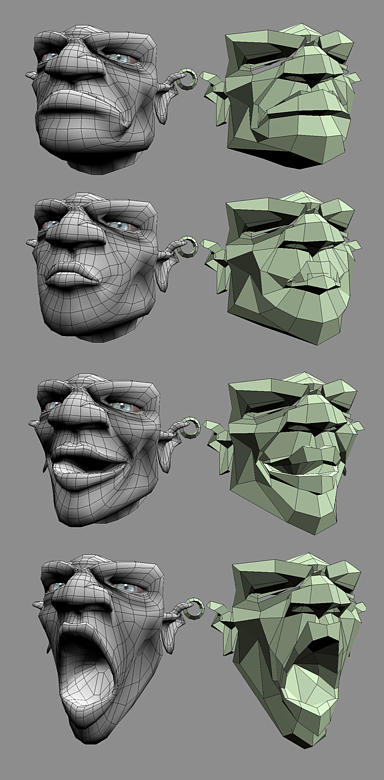 |
Figure 17. With well-designed edge loops, even trouble areas such as the corners of the mouth can be posed into any position without creating problems for the model's silhouette, contour, or movement. |
Raising the Bar
To produce high-quality work, content developers working in 3D face not only technological and aesthetic challenges. They must cultivate an understanding of the traditional techniques of sculpting, composition, and painting. Working with a computer doesn't exempt you from these considerations. Rather, it gives you a more powerful and flexible set of tools with which to master age-old artistic skills.
Because it both mimics and extends the traditional sculpting process, volume modeling provides a direct path toward this goal. Working on the computer lets you reach an aesthetically pleasing threshold so quickly that your only option for growth as an artist is to raise the bar. We hope the techniques discussed in this article help you do it.
Bay Raitt is a digital sculptor and animator/director, currently working on the Lord of the Rings project with WETA. He has previously been Engineering Product Specialist at Nichimen Graphics, lead modeler at San Francisco-based Protozoa, audio engineer, and comic book color separator (Spawn, Akira, Pitt, and MAX). He currently is involved in the quest for the perfect 3D pencil.
Greg Minter is the senior writer at Nichimen Graphics, responsible for all the documentation in Mirai.